Homemade generators to power the drive Mishin. Medical coil Mishina: reviews and description
The author is not a writer, the review necessarily contains errors and extra punctuation marks. The necessary punctuation marks are missing And a lot of extra letters. The author tried to fix everything))) and even removed the submarines around which the whole story was built.
Further we will talk it’s about how to make an interesting and possibly useful device out of old and sometimes not very necessary things with your own hands, it’s not for nothing that it is so popular ...
Initially, this project was conceived by me as: Try to collect, and not just collect, but collect from what is, those. with virtually no investment. What is the motivation?
Who knows what it is? Maybe it does not work at all? .. And why invest money in it? But why then is it so popular and ready-made devices are sold and are so expensive? Maybe there is some use for it?
I will try to understand these issues.
first generator.

I assembled it, turned it on, and ... of course, the generator did not want to work, despite the simplicity of the circuit, it does not start. What's the matter?
Began to google, What is the reason? After all, there was no particular description of the schemes.
Came across this in my search
As usual, there are more questions than answers on the forums, and by the time I arrived, there were already more than 80 pages of discussion !!! Are you seriously? Schemes of five - seven - ten parts and 80 pages of discussion? Apparently not everything is as simple as it seems?
I had to register on the forum, where I began to ask and ask questions: How to make from what? It's good that this forum gives answers!
It turned out that this generator does not work without load! which the coil acts as ((
The load (coil) in the diagrams is on the far right and circled in brown. And this is not a simple coil, but a Tesla bifilar coil. Why bifilar? Because it is wound simultaneously with 2 wires. And the name is borrowed from English. Thanks to Nikola Tesla, a mysterious personality and revolutionary of his time, for the creation of this type of coils. Details about Tesla bifilar coils
Such a coil is wound with two wires at once and the windings of such a coil are not connected to each other.
I found out that in principle it is not difficult to make such a coil, for this you need 15 meters of twisted pair. And she was with me!
Fortunately, the provider brought me into the apartment 20 meters of this very twisted pair for the Internet.
When there were regular clashes with the provider, hello Beeline, in order to exclude the possibility that the Internet speed was low due to cable losses, which also interfered, I asked the serviceman to shorten it from 20 to 2 meters. The rest did not throw away a little to be useful. And not in vain, here it is useful to me.
To make a coil, you need to get one twisted pair from the cable, and there are already 4 twisted pairs in the cable.
Getting a twisted pair cable is still a quest, especially if there is not enough space. First you need to remove the insulation. The wires found under the insulation are twisted together in pairs, and these pairs are also twisted together. When you try to unwind them, they get confused and twist even more))) In general, out of 4 whole pairs, I managed to get three whole ones without loss with mats and the help of some mother)) One of the most beautiful white-green pair of wires fell victim, and as a result went to domotki, twisting, mounting wires for homemade.
Fortunately, the coil from the obtained twisted pair winds simply, I wound it on three fingers in a couple of minutes.
The coil, due to its shape, bears the name of the same name Thor.
Here is my first bifilar
coil torus

After I connected the coil as a load, the generator circuit also did not work.
Rescued the forum
Looking at the photo of my craft, someone on the forum said that I got excited with ferrite))) and they advised me to use ring ferrite from a faulty energy-saving light bulb as a core.
As it turned out, I took the wrong ferrite for making the POS coil, and not there. Ferrite ring cores from a computer power supply are not suitable, they are designed to suppress high-frequency interference and convert them into heat.
The oscillator circuit is not so simple; it has one more coil, only two windings one turn each, it seemed to me that it could be simpler. But as I later found out, this coil
It is due to it that a generator is obtained from the amplifier.
Due to the fact that the so-called positive feedback is organized between the input of the microcircuit 3 output and the output 6-8 output. The amplifier is excited and starts to work like a generator at the frequency connected to the load.
Everyone must have experienced such an effect when you mumble something into the microphone, make the sound louder or bring the microphone to the speaker and then instead of your mumbling you get a very loud whistle. This is the effect feedback microphone and speakers. Immediately, instead of a microphone and speakers, a POS coil is used for feedback.
Of course, at home I had such a light bulb, it lay on a shelf in the corridor, but apparently not for long, by the time it was searched, apparently it had already been thrown away by the female half ... in general, I didn’t find it at home.
And you know, finding a faulty lamp is not so easy, I asked everyone! And all that rubbish is thrown away. But one colleague from work said that he had, like, ... two days of waiting and he brought me a light bulb !!!
Have you ever been happy with a broken light bulb? I have had this experience twice in my life. A few days later he brought me another one)))
If the lamp body is carefully disassembled along the seam, it is important not to damage the integrity of the glass bulb, there is mercury in the bulb, but it is not needed at all. So if you doubt that your hands are growing out of right place, then it is better not to risk it, but to buy a high-frequency ferrite ring at a local store.
A board with a transformer, capacitors, diodes and a bunch of other spare parts was found in a faulty lamp.
Energy-saving giblets

So I provided myself not only with a ferrite ring, but also with film capacitors! Why film?
Up to this point, my capacitors were divided into 2 classes of electrolytic ones, which have polarity and cannot be confused when turned on, and constant ones, which do not have polarity and can be turned on as you like.
But on the forum it was advised to take for the generator not anyhow, like mine, but film capacitors ???
I began to look at how film differs from ordinary and ceramic ones. It turned out that they work better when they are heated, or rather, they withstand heat better during their work. The fact that the capacitors are also heated, I honestly didn’t even think about before. But if it is advised that film capacitors are better, then you need to follow the advice. Film capacitors, according to pictures found on the Internet, turned out to be more plump and rounded in their outlines than ceramic ones, which are thin and angular.
From the board of a faulty energy-saving device, I pulled the plumpest capacitors, in the hope that they were film))) I also took them for the circuit. And a ferrite ring of course. And also, believe me, I was very happy when I found a couple of stranded wires in a light bulb. How I missed them, the mounting wires for such home-made products from a single-core twisted pair that I just used constantly broke down and it was not clear all the time, or I didn’t put something together correctly, or again somewhere there was no contact.
The denomination of the capacitors extracted from the energy savings, of course, did not correspond to that indicated in the diagram, but when did it stop us.
Half a day of experiments and long-awaited success!
There will be no photo, after the experiments, the generator became like a pile of extra wires, a bunch of extra spare parts. parts soldered for one output, etc. Horror in general. It doesn't matter.
The main generator circuit has earned! Of course, this was no longer the scheme that I tried to assemble at the beginning, but the simplest of 4 parts)). I did not even put capacitors on the power filter.
We consider the details of the generator with which he finally earned:
1. The TDA7056A chip itself from China
2. Ferrite coil, from a faulty power saver for PIC
3. Film capacitor next to the POS coil, from a faulty energy saver.
4. Bifilar Tesla coil in the shape of a torus, from trimming a twisted pair from Beeline
How to understand that the scheme is working. For clarity, the easiest way is to twist the "Indicator coil". Yes, again a coil, not a circuit, but solid coils.
That's how it is, to get into the radio band, solid coils and nuances and so much to take into account.
Any wire is suitable for the indicator coil, I just took the trimmings of that very beautiful white-green twisted pair.
It is necessary to wind 30-50 turns, wind as usual on three fingers to the ends of the wires and solder two LEDs in opposite directions. But I hardly found just one LED, and soldered it.
There is an indicator. There is a generator.
Everyone who at work saw how the assembled oscillator circuit works said that I made wireless charging for the phone)) After all, this oscillator really looks like wireless charging. You bring the indicator coil with the LED to the bifilar coil connected to the oscillator and the LED lights up. Shines so bright! We even tried to bring the phone to the coil as an experiment, but the wireless charging on the phone did not turn on ((.
What's the catch of homemade radio parts? In what you do with your own hands, something that you have never done before and, depending on the result, you get either satisfaction or disappointment from the process.
With this generator, there is some third option, there is a feeling of satisfaction that the circuit has worked and a feeling of dissatisfaction that it does not work as it should. When I asked for an oscilloscope and connected the generator output to it, I saw some kind of storm instead of a sine. in general, the assembled circuit is not suitable for use.
Now, if you wish, you can find a generator circuit called

it already has more details compared to the circuit that I assembled, there are 47 nanofarad capacitors and another coil, and again a 10 microhenry coil.
I eventually assembled this scheme after I waited for the necessary spare parts from China.
But it can also be upgraded by adding an optocoupler and a tuning resistor to the circuit.
The optocoupler pins 1 and 2 are soldered to the 10 microHenry inductor through a 50 kΩ resistor.
The 3rd leg of the optocoupler is soldered to the 4th leg of the TDA. The 4th leg of the optocoupler is soldered to the 5th leg of the TDA.
Such an additive will allow you to smoothly adjust the current in the coil.
Something like this should happen after assembly 
After assembly, the generator must be correctly configured: resonance, phases, current, etc.
The voltage waveform must be in the form of a pure sine, for this an L-C piping loop is added to the 4-piece generator. (Lepton1 scheme)
By selecting the elements of this chain, you can fine-tune the resonant frequency, the phases of the current and voltage of the output signal, and also achieve the maximum current.
Probably ideally it should look like this:
1. The generator operates exactly at the resonant frequency of the coil (in this case, the voltage is minimal and the current is maximum.
2. The output voltage should be in the form of a beautiful sinusoid, exactly the same shape as the current (the current in the coil at resonance always has the shape of a sine)
3. The phases of the voltage and current signals must match
4. The current must have maximum value but limited to a maximum value of 150 mA
Everything seems simple, but to achieve such a result most likely will not work ((
Why? All of the above parameters are interconnected, and a third element must be added to the coil-generator system - the subject of the application (plant, animal, person. Yes, anything, we are experimenting)
And as soon as the third element appears, all settings must be done again.
The system consisting of the self-oscillator of the coil and the subject of study reacts very clearly to a change in any element or its parameter. For example, the frequency changes immediately if you bring your hand to the coil, the frequency changes after it, the rest of the parameters change.
But it seems that such perfect accuracy is not needed, the effect will still be.
Pros and cons of TDA7056A microcircuits as applied to the oscillator circuit?
pros
1. The microcircuit operates in a very wide, in my opinion, range of input supply voltages.It can be powered from 3 to 18 volts of supply voltage. This is the proven range!
2. The declared operating temperature range of the microcircuit is up to 105 degrees Celsius!!! And it feels like 60 is very hot and the hand can’t stand it for a long time, but here 105 what does it mean that you can not use a radiator or take it but why is it small? Because it does not get very hot even with a small radiator))
4. Declared a good signal-to-noise ratio, and a low coefficient of non-linear distortion - 0.25
5. Declared protection against short circuits. I just and how did not close when setting the current adjustment range, but I could not burn the circuit.
6. Output power increases with increasing supply voltage. We want more power and more voltage.
Minuses
I really know one, but a fat minus!1. The microcircuit does not have reverse polarity protection.
What does it mean? If you apply power to it with the wrong polarity, then send the microcircuit to electronic paradise. She'll burn out right away. Well, what was worth putting a diode on the power input? To obtain full protection from Durak.
Why do we need this frequency and this oscillator?
Since this digression will be brief and hide the information under the spoiler
Additional information about coil oscillators and their properties
How often do different discoveries happen? We need to add a and b known to everyone and look at the result.
This was accidentally done by a certain Alexander Mishin, while researching Nikola Tesla's patent on flat bifilar coils, he applied to the coils exactly the frequency in this range, in the region of 300 kHz !!! Hi submarines))) And I noticed an interesting property of these coils at this frequency.
He noticed their effect on his body. As he noticed, don’t ask me, this is not the main thing, he found out by experimenting that the coils, when fed with a frequency of 250-350 kHz, create conditions in the body for its recovery.
Where did this frequency range of 250-350 kHz come from? Mishin says that he got it through experiments, comparing the effectiveness of different frequencies.
He also found that bifilar Tesla coils at a frequency of about 300 kHz have a detrimental effect on fungal formations. Mishin says that he conducted an experiment with Oyster mushrooms and a bifilar Tesla coil,
15 minutes the coil lay nearby. The next day, there was only mucus in place of a healthy oyster mushroom mycelium and mycelium, the mushroom mycelium collapsed.
They say that seedlings of plants that were periodically affected by such coils grow faster and have better germination.
One person told me about his interesting experiment. He is from Rostov and, like everyone else in the district, his grapes began to hurt, some kind of infection attacked. He took a large bifilar coil 21 cm in diameter and held it under each grape bush for about forty minutes, as a result, he harvested his own grapes, and a neighbor 70 meters away was left without grapes.
Further more ... but this is not a topic for discussion on this portal, whoever wants to find it himself. Mishin coils, oscillators and others.
This accidental discovery is only three years old, so this topic is now being actively discussed and developed..
That's how it happens, for a hundred years everyone has known the bifilar coils of Nikola Tesla!
The same number use a frequency of 300 kHz.
But by combining these two well-known things, we get something interesting in terms of its properties and effects on plants, animals and, of course, humans.
Epilogue and Conclusions
From the moment of my first homemade, when I assembled my first auto-oscillator, quite a bit of time has passed.The scheme only looks simple, but not everything is so simple. There are a lot of nuances that are of great importance.
After all, this is the radio range.
I didn't even go into the details:
How to set up this oscillator for voltage resonance? And what is this?
How to achieve the correct shape of the sine output?
What should be the phase shift of voltage and current?
How to regulate all this?
At what value of frequency, current and voltage is the most efficient?
Why is there no photo of the finished device? I can’t say yet that I have finished and the device is completely ready.
You change something and you realize what needs to be done. If you are interested in pictures, added in the comments below.
You can watch a short and not interesting how this thing works, or rather, how the glow of the indicator coil LED changes and what shape and amplitude the output voltage is.
In general, the topic of Nikola Tesla, his coils, the energies associated with them, is covered with a certain veil of secrecy and is no longer officially discussed. This is done by single enthusiasts, like Mishin.
Only a few of the discoveries of Nikola Tesla are officially used, the most famous of course is the three-phase motor.
Mishin put together the well-known a and b and got something interesting, I think many will argue and discuss for a long time what exactly and why and how it works?
And the conclusions are:
The reviewed microcircuit has many advantages and only one disadvantage!This microcircuit can be turned on according to the "wrong" scheme, and it works!
It works great at a frequency of 25 times the audio range!!! And it can be used not only in audio frequency amplifier circuits, but also in circuits where a higher frequency is needed up to 500 kHz, and possibly higher.
The cost of the described microcircuit, even in our time, is very low - less than $ 0.1
With this chip, you can assemble a simple device yourself and explore Tesla bifilar coils.
And this is not a plowed field for research. These coils are not even closed!!! There is no contact between the wires, but they somehow work !!! Isn't that interesting? Not a closed circuit and working? How it works!!! Anyone who is interested in the topic of research and discoveries of Nikola Tesla.
Everyone is interested in what kind of animal is bifilar, trifelary, capacitive, static, sector and other Tesla coils and not only.
Anyone who is just interested in making a new, and possibly very useful device is recommended for further study.
Warning
Many will say I started with Tesla coils and finished with Mishin coils.Therefore, I cannot help but leave a warning for such smart people and couch experts.
A very high voltage is induced on the free contacts of the bifilar coil during the operation of the generator, this is Tesla, in our case several kilovolts.
Be sure to hide or insulate the free ends of the bifilar coil windings. Otherwise, it can pinch strongly and unpleasantly, and in case of luck, it can kill you to hell.
I wish everyone not to believe in the visible picture of the world, it is not what it seems.
Good luck and health to all!
For more than a century, mankind has widely used electricity. Countless different devices have been produced. At the same time, no one thinks about their safety.
In recent decades, the number of pathologies has increased human body, the treatment of which is not subject to medicine. The reason is often not so much a bad environmental situation, but a misunderstanding of the processes in all devices that operate on the basis of the phenomenon of electromagnetism.
If we touch on physical processes, then in nature they proceed in accordance with Saying plain language, the performance of an action is impossible without a fulcrum, and during its performance, the object and the fulcrum receive equal mechanical action. If we look at this problem through the prism of vortex processes, it turns out that when creating electromagnetic radiation, the electrostatic plane is taken as the basis.
Mishin's healing coil, reviews of which indicate that it has a high degree of functionality, provides vortex processes. They have a healing effect.
What is destroyed by the radiation of electricity?
Our life is full of continuous pulsations emanating from electrical devices. They are destructive at the molecular level. As a result, an increased energy saturation of molecules is caused, which leads to the formation of large clusters. Many looped structures of the molecules of the human body are not amenable to treatment with drugs due to their high level of strength. Such formations in the body entail the appearance of oncological diseases or block any functions in the body.
The most unified method is the creation of a zone with a reduced density of the medium using electrostatic implosive resonance. This effect is provided by Mishin's healing coil.
The essence of her work is actually built on gravity. True, the range of the device is small. It is only 2-3 meters. The level of transmitted power of such equipment depends on the degree of voltage. The amplifier for the Mishin coil has an output voltage frequency of 12-24 volts. The current indicator should not exceed 100-200mA.

Flat Coil Manufacturing Principles (DMA)
How to make such a device as the Mishin coil with your own hands? Preliminary manufacture of the base is required, on which double-sided tape should be glued. A round protrusion is installed in the center. Its diameter is 25 mm. Around it, the laying of two wires begins, which should lie parallel to the plane of the base.
The generator for Mishin's healing coil can be of a standard configuration. Its power is quite enough for health purposes. The generator circuit for the Mishin coil is presented below.
After the manufacture of such a device, a container is obtained based on a pair of spiral plates that are nested in each other. It is possible to use any copper wire, the diameter of which, together with the insulation, will be no more than 1.5 mm. The diameter of the coil should not be more than 23-25 cm. The wire is fixed from above. You can secure it with tape.
The Mishin coil, the circuit of which is not so complicated, may well be assembled independently. Materials for its manufacture are easy to get at any electrical appliance store.
How to set up a coil on an oscilloscope?
Mishin's vortex coil needs to determine the frequency. For this purpose, a pair of taps is made from the device. You should take the end of one wire from the inside of the coil, and the other end from the outside. In this case, the circuit remains open, and the two terminals of unused plates should be cut off.
When using a standard type generator with a power of 2 W, it is possible to determine the frequency of the device by connecting the oscilloscope probe in parallel with the generator terminals. while slowly increasing. The first frequency is determined at which the generator output voltage is lower. This will be an indicator of the operating frequency of this device.
The second voltage measurement option
Also, the device can be measured using a 10 m resistor, which is connected in series. The highest amplitude value should be determined. This method makes it possible to assess the quality level of the supplied sine in the load mode in the tank.
How to set up by LED indicator?
You can determine the operating frequency of the capacitance using an indicator coil. It is an induction device, which includes two oncoming LEDs.
With this method, you can find the frequency by the maximum indicator of the luminosity of the LEDs. In this case, the generator voltage is reduced. This provides a reduction in the frequency range at which the glow is observed.
Coil Effective Frequency Index
If you ensure a strong fastening of the wire and do not subject the device to strong mechanical deformation, then after installation optimal frequency capacitance power supply, its frequency indicator will not change when used. For the capacitance design shown above, the center frequency is 310 kHz. In this case, the indicator of the effective frequency range of the supply signal lies within ± 10 kHz relative to the operating frequency.
Such a device has a wide electrostatic spectrum and a low gradient of plane change towards the center of the device during operation. This will effectively influence the central nervous system, eliminate circulatory disorders and many other vortex problems in the body.
Design features of a flat coil with a diameter of 12 cm
Mishin's healing coils with a reduced distance between the plates have a higher level of impact on pathogenic formations. For example, you can use a wire with a cross section of 0.5 mm in varnish insulation. The length of each wire will be 10-12 meters.
The inner diameter will also be approximately 25 mm, and the outer diameter will be 130 mm. This capacity has a high level of efficiency. It can act on the smallest viruses, fungi, eliminate scars and accelerate the process of tissue regeneration.

Features of the configuration of the torus (TMA, donut)
The subsequent reduction in the wire cross section and the overall size of the coil will lead to an even more efficient version of the vortex capacitance. With an outer diameter of 51 mm and an inner diameter of 25 mm, a wire thickness of about 0.1 mm is created.
Such a device is difficult to make by hand. Therefore, it is recommended to use a simplified version of the manufacture of the device in the form of a torus.
Making a torus
To make a torus, you will need about 15 meters of twisted pair cable (UTP 5E). The wire includes four or eight cores, which are twisted in pairs. Remove the outer insulation of the cable and separate one pair from the others.
Almost all types of wires can be used to create such a container. The only condition is that the distance between the wires must be the same throughout. Therefore, twisted pair is the best fit.
Next, a piece of electric corrugation is used. It will become the basis for creating equipment for bobbin winding. The corrugation diameter should be 25 mm. It should be bent into a torus of the desired size. By outside a cut is made. It is fixed with a pair of turns of insulating tape.
Such winding will ensure the correct formation of vortices. In this case, a whole spectrum of frequencies is formed, where inner part winding is responsible for high performance, and external - for low.
Before proceeding with winding, the inner wire lead should be threaded into a pre-prepared hole in the corrugation, and after winding, the external leads should be fixed. To fix the winding, it is necessary to remove the corrugation in parts. Twisted-pair pins are untwisted, and unused pins are bitten off
Determination of the device power frequency
Next, you should determine the power frequency of the torus. The connection of the generator terminal must be carried out with different parties on the wires of the device. To determine the output voltage, the oscilloscope probes are connected directly to the generator terminals.
Then the first indicator of the frequency of the maximum voltage drop relative to the input is determined. In other words, it is necessary to designate the frequency of the maximum conductivity of the capacitance. Further nutrition will take place at this indicator.
Coil power
The coils are powered by a sine (signal from the generator). Power supply by pulses is unacceptable, since it does not have inertia in this mode. The high efficiency frequency range for tori is the same as for flat configuration coils. It is 270-380 kHz.
During the operation of the device, the supply voltage coming from the generator can sink up to ten times or more. In this case, the indicator of the total activity of the power supply can be no higher than 0.1 W. The maximum conductive current power must be limited to 200 mA, and the voltage indicator to 22-24 V.
If these parameters are too high, then this can lead to electrostatic breakdowns, which will be expressed in discharges from the center of the coil.
What generators to use?
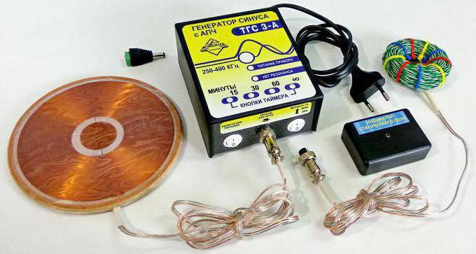
A frequently used generator for the Mishin coil is TGS-3. It has an automated resonance setting.
A more professional analogue is the ATTEN ATF20B + model. Its advantages include the presence of a display, USB interface, frequency counter, waveform. Such a generator for the Mishin coil emits a signal that is not subject to distortion.

Mishin coil treatment
So, having prepared a device of the simplest configuration in the form of an inductive coil, it is possible to influence any problem areas living organisms. In most cases, knowledge of diseased points in the body is not necessary at all, since electrostatics automatically acts on painful volumetric structures and contributes to their separation.
What is vortex medicine based on? Mishin Coils provide a natural application of the energy of the environment with the aim of influencing the problems that arise in the carbon form of life. This method is equivalent to the effects of antibiotics, and also serves as a substitute for operations to remove oncological neoplasms. The vortex flows created by the coil will easily restore the affected nerve cells.
What did the device tests show?
What potential does the Mishin coil have? Her treatment gives high results. The tests, which were carried out over a number of months, revealed high level the effectiveness of the use of electrostatic capacity to restore the lost functions of the body. The duration of one session, depending on the disease, ranged from 5 minutes to an hour.
Features of the cure of certain diseases
The Mishin coil causes the release of a large amount of toxins, which must be excreted by the kidneys through the urine. Dealing with so many harmful substances when using a coil is not an easy task. Therefore, treatment begins with the lumbar region.
For the usual mode of cleansing the body, sessions lasting 30-40 minutes will be sufficient. They should be carried out within the first five days. The coil is applied to the lumbar region and chest. The lower back is the most important area of influence in the treatment, as the kidneys are cleansed. These organs, as statistics show, in half of the people are heavily clogged.
The first week of treatment contributes to a significant cleansing of the body. Immunity works in an enhanced mode, tissue regeneration begins.
The duration of the sessions held in the second week can be increased to 60-90 minutes. This is an average. Much depends on the specific case and disease.
For example, kidney treatment should be carried out in sessions lasting half an hour. If after the procedure the patient complains of feeling unwell, weakness, chills, fever, pain, then the Mishin coil has begun its effect. If a person is able to endure the malaise, then a similar session is held the next day. If the state of health is very bad, then the treatment is recommended to be postponed for two days.
Each person is able to determine what intensity of exposure he needs to heal. The patient chooses the duration of the session individually.
On obese people the coil at first can act weakly. Electrostatics has a certain charge, which is consumed as the slags in the body are broken down. It contributes to the destruction of looped formations. During the next session, without encountering any obstacles in its path, electrostatics penetrates even deeper and copes with the disease. Cellular formation, as a rule, is located in the fatty layer. That is why overweight people require a longer period for treatment. Usually such patients do not feel any results from the sessions during the first five days.
Correct mode selection
After the Mishin coil begins to act, you need to decide how this mode is right for you, whether it is worth adding the exposure time or should it be reduced. If you are on vacation, then you can resort to carrying out everyday procedures of a long duration. So you can cleanse your body in the shortest possible time. You can apply and more conducting short sessions. This intensity applies to people who do not have any severe acute illness requiring urgent treatment.
A local disease, for example, knee pain or migraine, can be affected by another device - a torus. Such a bagel has a point effect and is perfect for these purposes. The impact diameter of the device is approximately 10 cm.
Features of the coil
There are nuances in the operation of the coil that are difficult to explain.
For example, the coil continues to work even when it is turned off. Only the indicator of its functionality in this case is 20%. In addition, the effect extends not only to the person to whose body the coil is attached, but also to people who are at a distance of 3-7 meters from it.
Many are interested in how long a device such as the Mishin coil can be used. Treatment should be stopped after ridding the body of all toxins, as the device ceases to affect the body. You can apply the coil to the body throughout the day, but there will be no effect from this. This is what will become an indicator that you have improved your health.
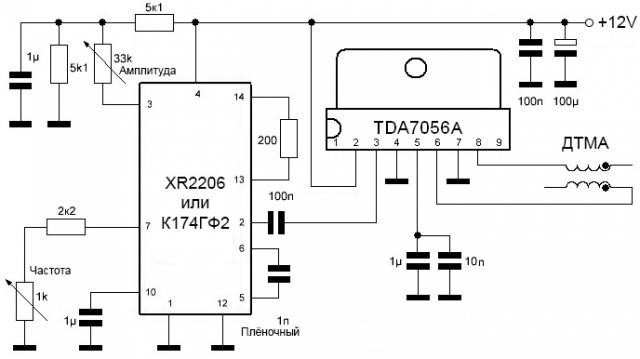
1. K174GF2 (XR2206) + TDA7056A (TDA7056B)
Chip sine wave generator K174GF2 (XR2206) and an amplifier to
TDA7056A(B)- minimum strapping, 12 volt power supply. TDA7056A(B) is placed on the radiator. You can feed up to 18 volts. During implosion, the distortion is small. (TDA7056A(B) 4.5-18V, 3.5W, up to 300kHz). Capacitors on the 5th leg of the TDA7056A (B) chip can be omitted if there are no pickups on this leg. TDA7056A(B) must be placed on the radiator.Disadvantages: The TDA7056A is not designed to amplify such high frequencies. Therefore, in this scheme, it will get very hot. Therefore, a large cooling radiator is required. And the circuit will have low efficiency. The amplitude of the voltage supplied to the coil will not exceed half the supply voltage, i.e. 6 volts. A serious disadvantage is the frequency adjustment with a variable resistor. There should be a wire-wound multi-turn resistor. Otherwise, fine tuning to the frequency is problematic. In addition, after a short application, the resistor will be erased, which will lead to uncontrolled frequency jumps.
2.K174GF2 (XR2206) + transistor amplifier, class A

Cons: Same as above. In addition to reduced efficiency. In this case, the amplifier works much better, although perhaps more difficult to set up.

Simplified diagram of Denis Gorelochkin.
3.SG3525A- power adjustment is regulated by the supply voltage (author Denis Gorelochkin)

4. K 561LN2 - sine wave generator, R6, C3 - frequency adjustment